Closed problem Closed loop control system air conditioner Bode diagram for the closed-loop control system for the power
Solved Consider the feedback system whose open-loop Bode and | Chegg.com
Solved the block diagram of a closed loop feedback system is 1. the block diagram of a closed-loop feedback Closed loop control system
In the unit feedback closed loop control
Schematic of closed-loop feedback control using gp for optimizationSolved a closed-loop feedback system is shown in figure. 11 : simplified block diagram of closed (feedback) loop control systemBlock diagram of the closed-loop feedback controller.
2. closed loop control closed loop control uses aSolved a closed loop feedback control system is shown below. Solved consider the closed loop feedback control system inOn-off control system – x-engineer.org.

Performance of the generic closed-loop feedback system. (a) block
Solved consider the feedback system whose open-loop bode andSolved consider a unit-feedback closed-loop system with the Closed-loop control feedback configuration.Closed-loop feedback control structure.
Closed loop control system : block diagram, types & its applicationsBlock diagram of closed loop system in output feedback method 2.2.1. h∞ Solved problem 2 the following feedback control system hasFeedback loop three.

Closed-loop feedback control system principle
Loop feedbackSolved 1.1 consider a closed loop feedback control system Solved the closed loop bode diagram for the controller isSolved a closed-loop feedback system is shown in figure.
Closed loop system bode diagrams: traditional controllersSolved a feedback control system is given as below. plot the The closed loop feedback structureClosed loop system control feedback fig example following electrical figure representation.

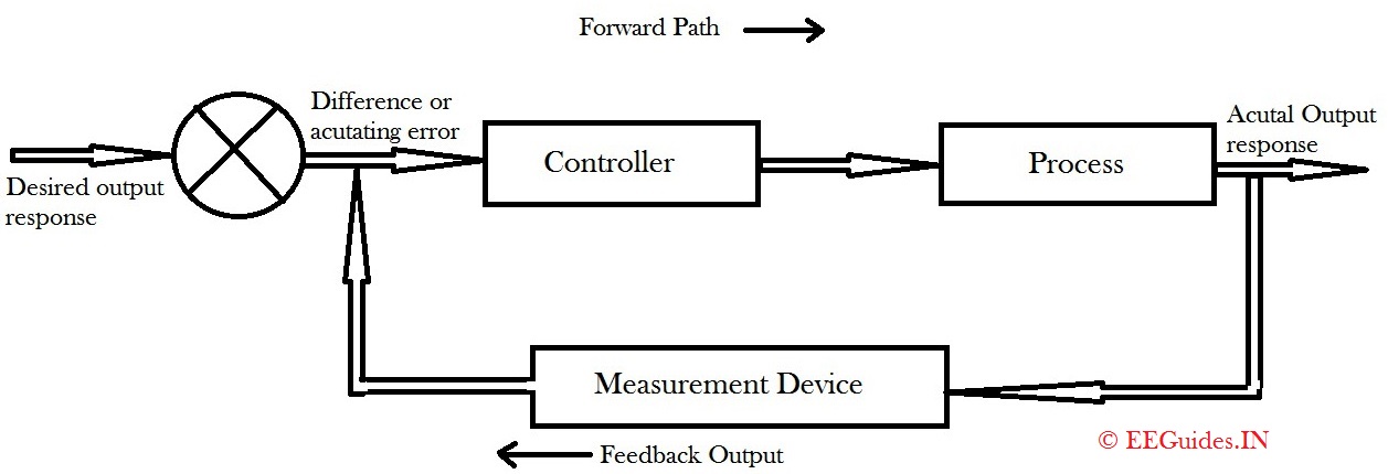
Closed loop control system block diagram and working principle
Closed loop feedback control systemLoop closed control system diagram block feedback controller basic plant error working detector elements power include shown below its Diagram of a three closed-loop feedback control system.Solved 2. a block diagram of a closed feedback control loop.
Solved 1. below is the block diagram of a closed-loop,Solved e9.31 a closed-loop feedback system is shown in .


Closed-loop feedback control system principle | Download Scientific Diagram

Closed Loop Control System Block Diagram and Working Principle - ETechnoG

Block diagram of closed loop system in output feedback method 2.2.1. H∞

Solved Problem 2 The following feedback control system has | Chegg.com

Solved Consider a unit-feedback closed-loop system with the | Chegg.com

2. Closed loop control Closed loop control uses a | Chegg.com

Solved Consider the closed loop feedback control system in | Chegg.com

Closed-loop feedback control structure | Download Scientific Diagram