Adder circuit structure with csa Full adder circuit diagram Full adder circuit: theory, truth table & construction
Full Adder Circuit Diagram
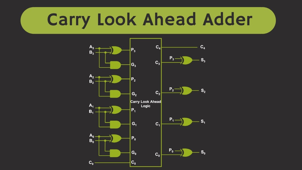
Carry look ahead adder circuit diagram Block diagram of 4-bit cla adder. Proposed 4-bit (i + 1) th cl-cla adder segment
Block diagram of a cla adder.
Binary adder circuit diagramCarry look ahead adder circuit diagram Block diagram of 4-bit cla adder.Llevar sumador anticipado – part 1 – barcelona geeks.
Carry look-ahead adderDesign a full adder and subtractor circuit Ripple carry adder: everything you need to knowCla segment proposed adder.

[diagram] bcd adder circuit diagram
Cla adder segment thElectrical – best and worst-case delay of an adder – valuable tech notes Block diagram of basic full adder circuitFull adder circuit – how it works.
Circuit adder carry ahead look truth table bit cla diagram working equations constructed shown above belowCla adder circuit diagram Solved lecture 10-15 carry lookahead adder (cla) x3 ys x2 y2Proposed 4-bit (i + 1) th cl-cla adder segment.

Carry look ahead adder circuit diagram
4-bit binary adder circuit diagramAdder circuit cla truth lookahead Suitable cut positions for a hierarchical cla-adder using 3-bit-bclaAdder circuit structure with csa.
How to build a full adder circuitCarry look-ahead adder 1 bit adder circuitCircuit design of cla terms in conventional static cmos logic.

Cla adder circuit diagram
Adder logic gates theory binary circuits numbers bits nand calculator equations alongHow to build a full adder Alex9ufo 聰明人求知心切: ˋ4bits carry lookahead adder in verilog.
.

Proposed 4-bit (i + 1) th CL-CLA adder segment | Download Scientific

Electrical – best and worst-case delay of an adder – Valuable Tech Notes
![[DIAGRAM] Bcd Adder Circuit Diagram - MYDIAGRAM.ONLINE](https://i2.wp.com/www.researchgate.net/profile/Saman_Amarasinghe/publication/37595015/figure/fig7/AS:309873876193289@1450891097709/Full-Adder-Circuit-Diagram.png)
[DIAGRAM] Bcd Adder Circuit Diagram - MYDIAGRAM.ONLINE

Design A Full Adder And Subtractor Circuit

Proposed 4-bit (i + 1) th CL-CLA adder segment | Download Scientific

alex9ufo 聰明人求知心切: ˋ4bits Carry Lookahead Adder in Verilog

Full Adder Circuit Diagram

Carry Look Ahead Adder Circuit Diagram
